In this post I’ll show how I built an ambilight alike system for my panasonic TV. I did this using and arduino controller in combination with amblone. This is how it’s described on their website:
Amblone stands for Ambilight Clone, and it is an open source ‘Do It Yourself’ solution for imitating Philips Ambient Lighting Technology. It projects light on the wall behind your TV or monitor in the colours that are currently on the screen. The lighting is achieved by a number of RGB LED strips that are mounted on the backside of the screen. The strips are
Shopping list
Alright, so what do you need to make something like that? Besides the arduino controller, you’re free to choose whatever brand or type you like, as long as it matches the technical specifications. This is what I used:
- 4x 12V 54-LED RGB Light Strip (50cm): EUR 37
- 1x AC to DC 12V 1A Power Adaptor with 5.4mm DC Plug: EUR 3.54
- 2x ULN2003A Chip: I got those for free, thanks Michael!
- 1x Arduino Mega 2560: EUR 47.50
- 1x Breadboard met Jumpwires: EUR 14.45
- Wire (4 wires for each strip)
In addition to the things listed above, I bought some stuff to build a nice enclosure:
- On/off switch
- Enclosure
- Power led + resistor
The total is about 100 euro or 125 dollar. If you want to cut back on costs, you could use an Arduino knockoff. If you would be unable to find the ULN2003A chips, an alternative would be to use regular transistors in combinator with 2K2 Ohm resistors. Everything was already ordered when I stated writing this article. The components from iPrototype should be arriving shortly, those from dealextreme usually take up to two weeks to arrive.
Electronics
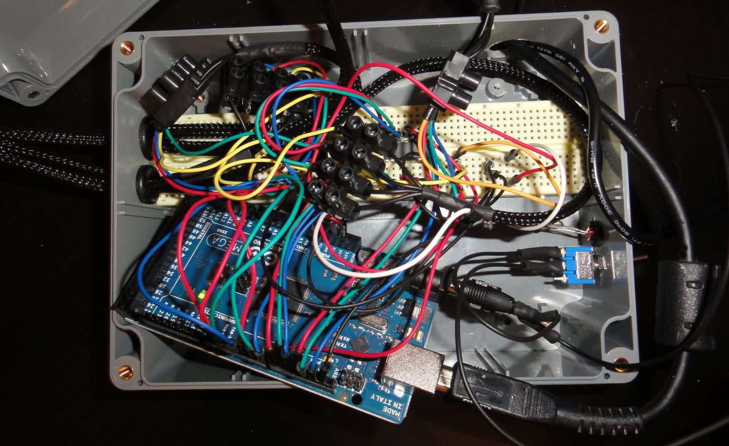
I used the ULN2003A AMBLONE V2 layout for my breadboard. You can download the .fz file and open it using Fritzing to see how to connect the wires. Here is what it looks like:
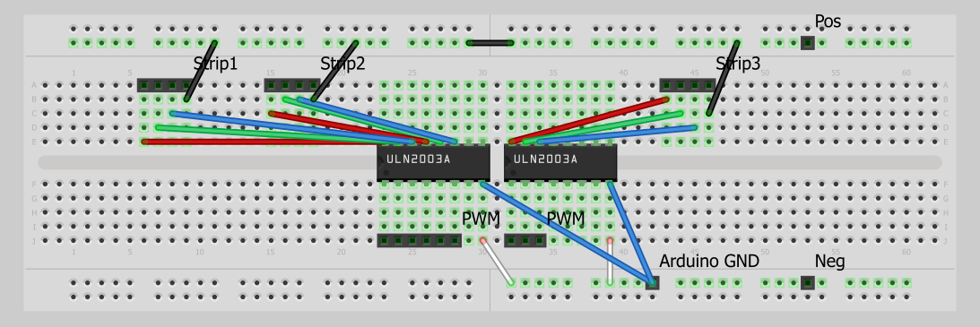
I’ll be using 4 LED strips, so both ULN2003A chips will be connected to 2 strips. This doesn’t change the design much: 3 additional connections on both sides of the chip. I chose to use a breadboard because I don’t have a lot of experience soldering. With a breadboard you can connect certain electronic parts using little wires. It’s commonly used for prototyping because it’s easy to disassemble the circuit.
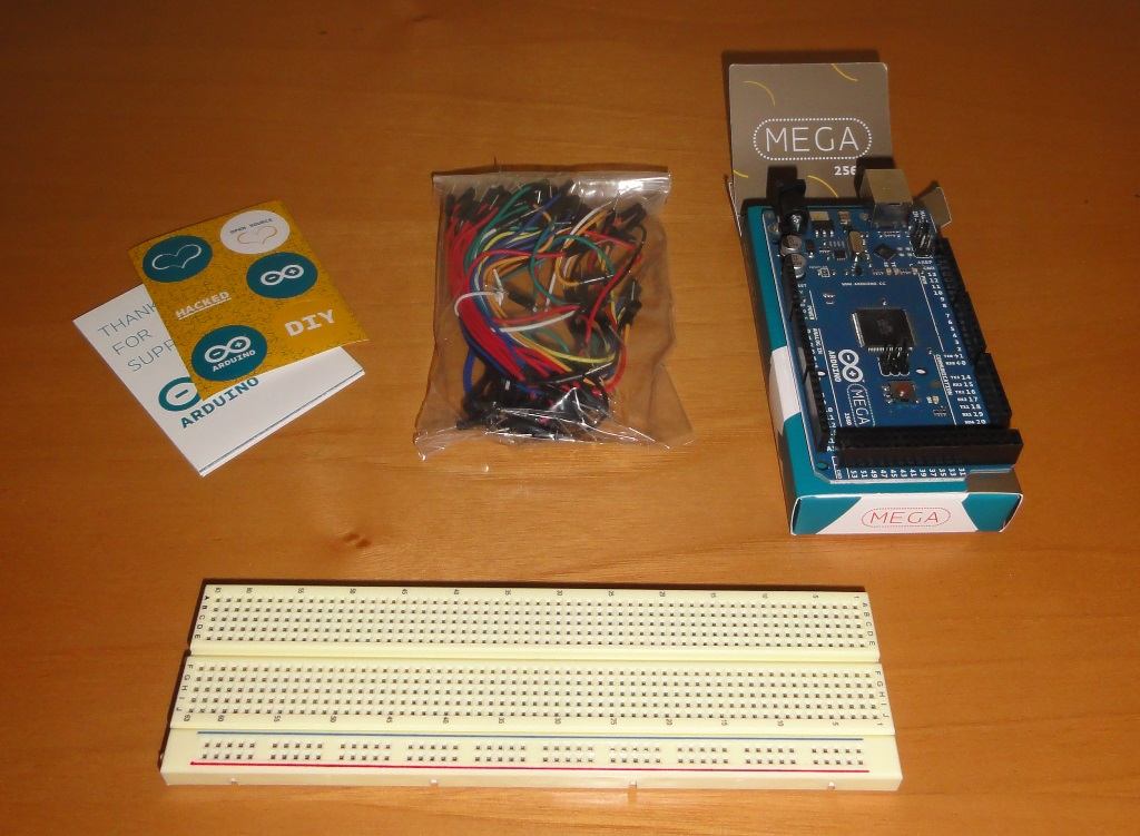
First delivery
Today I received an e-mail from DealExtreme to inform me my order was sent. There was even more good news: my order from iPrototype arrived! Everything was nicely packaged and it took only 3 business days: that makes me a happy customer! :)
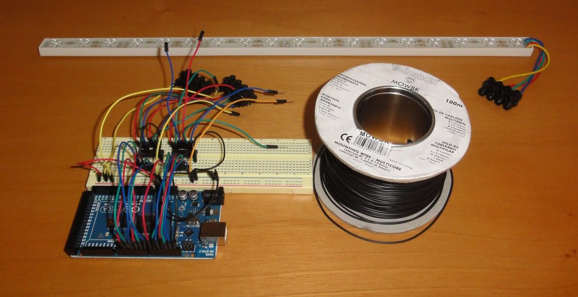
My LED strips left Hong Kong today (2011-11-20), I’m hoping for them to arrive withing a week. In the meantime I’ve been playing around with the controller. I bought some LEDs and resistors in a local shop and started writing my first lines of arduino code. The syntax is quite similar to widely used programming languages which lowers the learning curve significantly. Their website provide a decent amount of examples to start with and even more can be found on other websites. Within a few minutes you can build a simple circuit and program some LEDs to blink or fade. I have to admit: it is a lot of fun!
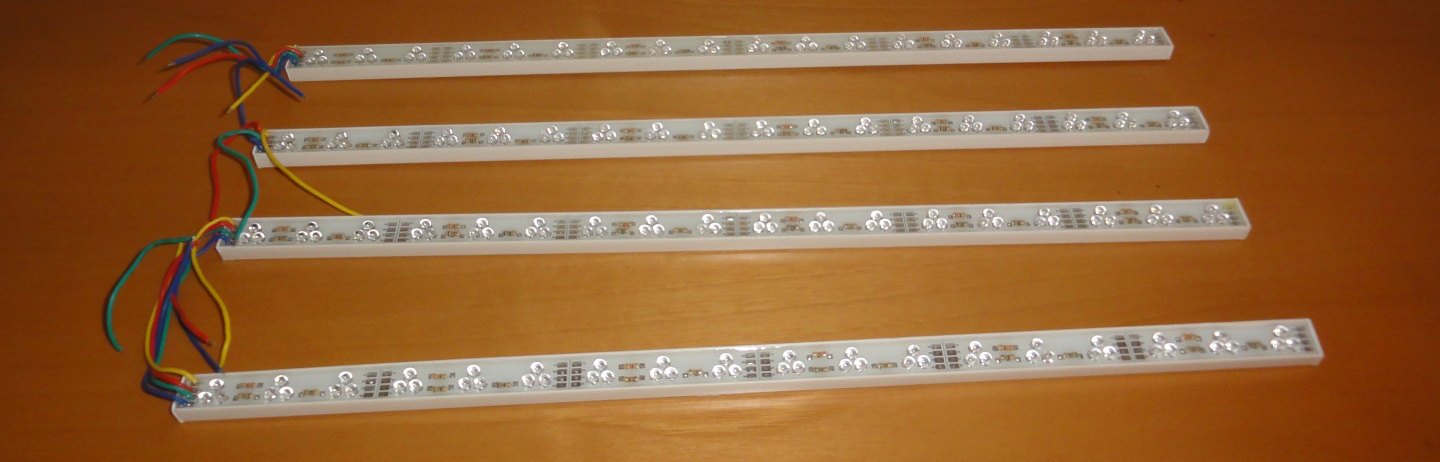
The second delivery
Woohoo, my package arrived! I immediately connected the LED bars to the controler to make sure nothing was damaged. Although they were protected by bubble wrap, you can’t be sure they were treated with care. It turned out they all work perfectly. Time to start building!
The first thing I did was connecting the 4 cables (R/G/B + Y) to a black screw-connector. I did this for every LED strip and did it again for all jump wires. Now I have 4 black connectors with each 4 different colored cables attached. To connect these I will be using some black wire I had laying around. It’s a composed wire with 7 x 0.193 mm internal diameter and a total of 1.4 mm external.
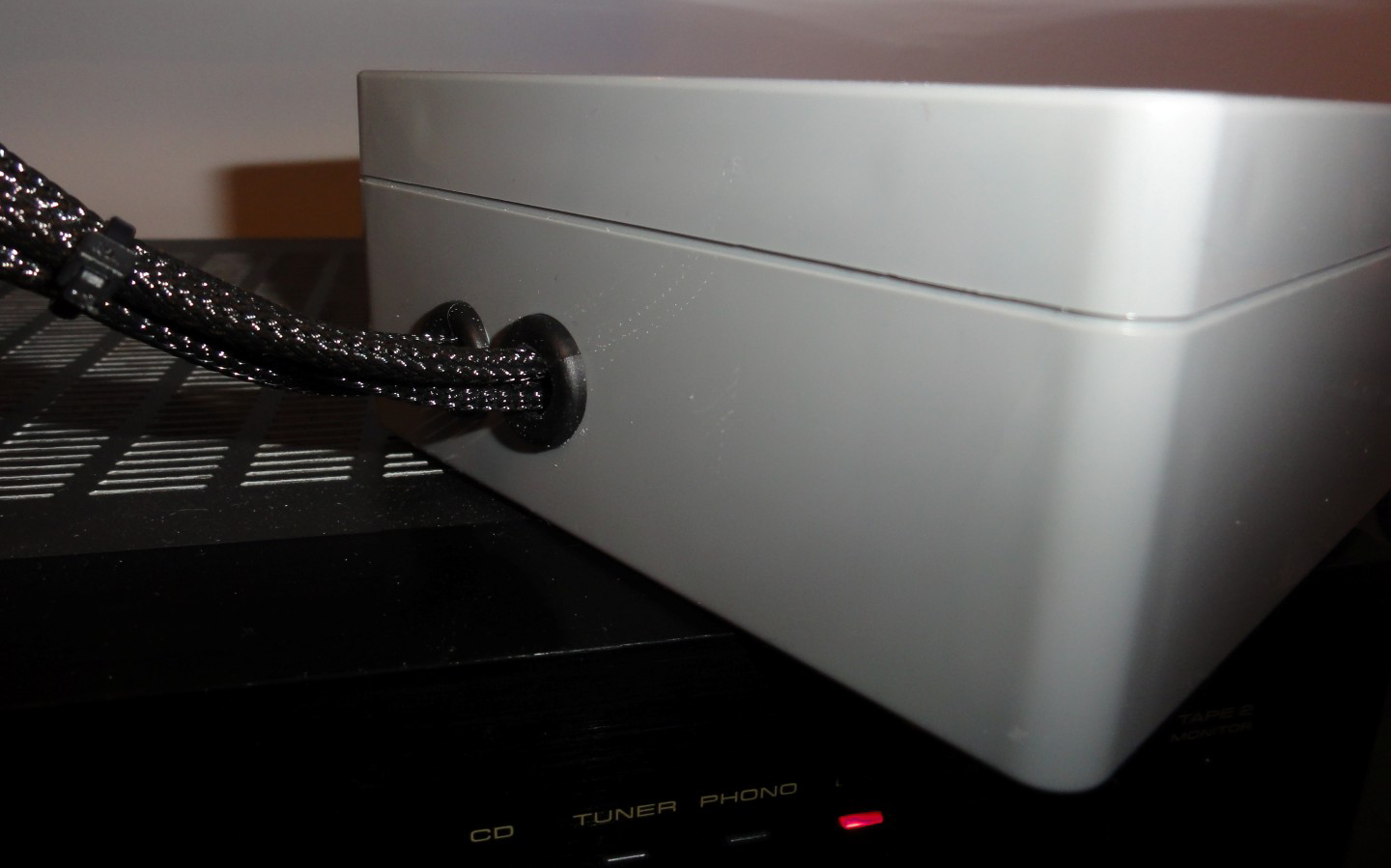
I had some MDPC-X sleeve left from my water cooling project and decided to use it to tidy up those wires. It went unexpectedly well and within a few minutes every 4 cables were sleeved. Before connecting the wires to the LEDs, I took down my TV and prepared it with Velcro. A long piece at the top and two shorter ones at each side. I was surprised by how sturdy it was: when I wanted to remove the LED bars again, I was almost bending them. I connected all the wires to the bars. I should have marked the wires, but I forgot to: now I had to try each one of them to find the shared positive. Once found I configured Amblone to show a static white color making all colors active.
Minor problems
I connected everything and it all worked perfectly. There are two minor problems though:
- I want to be able to turn of the whole system without disconnecting it from my computer.
- I don’t want me or my cat accidentally disconnecting some of the wires.
To solve this I went to the local DIY store and bought a switch and an enclosure. Of course this is completely optional. Feel free to use a cardboard box or something as enclosure. In my case I’ll be putting the whole system on my desk, so I prefer having it in a decent housing. I drilled four holes in the plastic enclosure: a small one for the switch, another small one for a single LED, one for the wires connected to the LEDs and finally one for the power and USB cable. I used some rubber rings to protect the wires from the rough edges.
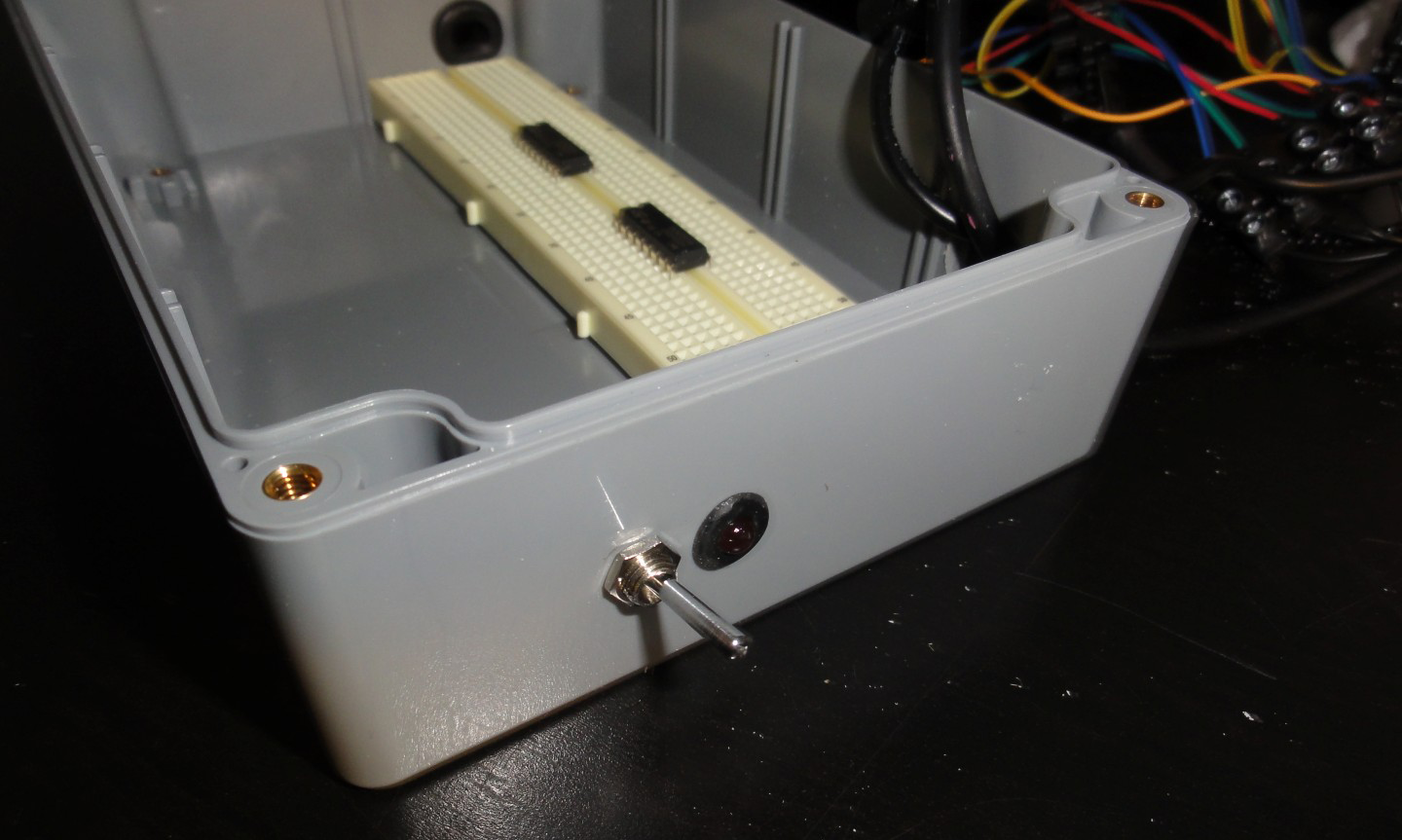
I disconnected the wires again to put them trough the hole. It turned out, however, it was way too small for 4 wires and the only solution was to drill another one. Luckily I had marked the cables this time. :) Last thing to do was to solder the red LED and the switch. It has been easily 5 years since I lasted soldered but it went pretty well. I managed to stuff everything (gently) together in the box and screwed the lid on.
The red LED is connected to 5V using a 220 Ohm resistor. It lights when either the 12V is connected or the Arduino is connected to the computer. I was hoping to only power it in the first case, making it a on/off indicator but I have no idea how to do this (yet).
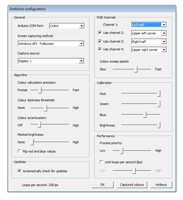
Software Configuration
This is how my Amblone setup is currently configured. As you might notice my Windows Color Scheme automatically switches to Windows Basic. This is because I wasn’t limiting the LPS, thereby doing an excessive amount of calculations. You can use the slides to limit the LPS, which should be around 30.
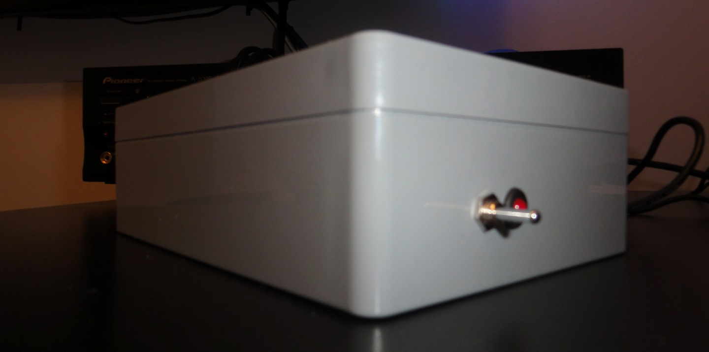
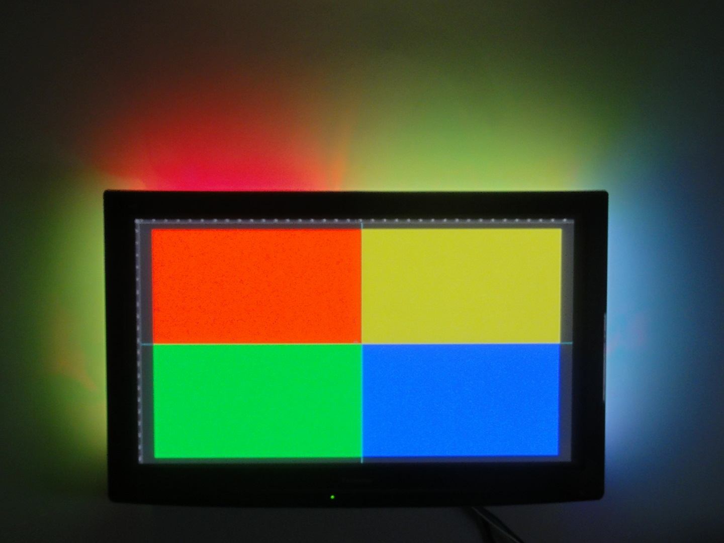
The Result
My camera didn’t manage to focus properly, but I’m sure you get an impression of the result.
Conclusion
I’ve been using my Amblone setup daily for over half a year now and it hasn’t failed me once. From what I can tell the software is very robust and so is the Arduino controller. It never takes me more than a few minutes to realize I forgot to switch on the ambilight. When I say I can’t image watching TV without it, you can take that literally.